
Are all buckboost converters bi-directional? A non-synchronous switching converter uses a diode for one of the switches. Such a converter typically transfers power in only one direction. (Is there a better term for this than 'non-synchronous switching converter'?) A replaces each of those diodes with an actively controlled FET. Such converters are inherently bi-directional and usually more efficient than non-synchronous converters. Do i still need transistors for the switches?
Or will the chip do the switching for me. If you only need 1 amp or so of input or output current, there are several switching regulator ICs available that have internal transistors that do all the switching for you. For example, you might look at the figure 13, which shows how to use that chip to produce 12 V regulated output from input anywhere in the range 8 to 16 V. (Alas, it is non-synchronous, transferring energy only in one direction).
If you need higher currents, you're pretty much forced to use external discrete FET transistors for the switches. The typical circuit is shown on the first page of the, which shows a synchronous (and therefore bidirectional) 10 amp switching converter. Recommend good topologies Some tips have been collected at. Simple uni-directional Buck-Boost without resonant caps using 'Supercaps'. Bi-directional Buck-Boost using resonant caps on each switch. (More efficient but more complex dead-time commutation control) Imagine a regenerative braking car in this arrangement with the battery voltage on the one side and motor/generator on the other side, and the demand to accelerate and brake the motor in an intelligent phase control controller (Not shown for simplicity). (There may be many parallel MOSFETS to reduce the Ron value).or a dual source power supply which can be charger on left and battery on right.
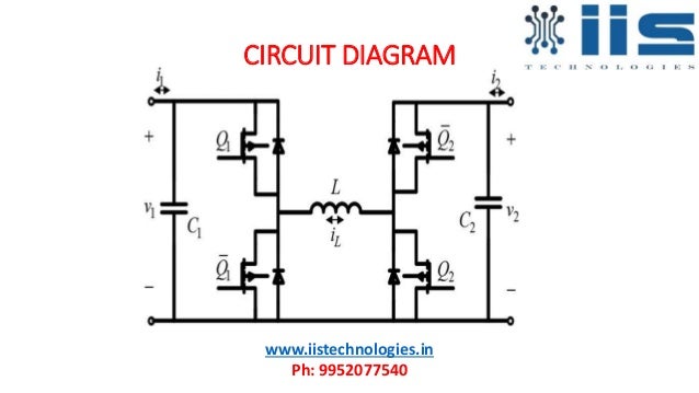
Isolated, and interleaved bidirectional DC-DC converter topologies relevant to interfacing various energy storage units to the microgrid will be reviewed in this section. Bidirectional Buck-Boost DC-DC Converter Fig. 2 shows a bidirectional buck-boost DC-DC.
These are some of the patented and licensed waveforms used to regulate the resonant switching commutation of the Buck-Boost high efficiency regulators. You can read the patent for theory of operation. This is just intended to wet your appetite of the complexity of a bi-directional Buck Boost controller switch. Nurarihyon no mago season 2 ova sub indo mkv. Voltage and current sensing is an important aspect to optimize commutation duration when the switch voltage drop is minimal. Resonant switch Capacitors & Diodes during free-wheeling play an important part in the commutation to make it loss free. These charts show the On state of each transistor with the thick bar, not the voltage or current.
Spellforce platinum edition trainer download. Made by Recifense Hi guys, Someone asked for this game, so here is my contribution for 'Spellforce - Platinum Edition' Version 1.54.75000. The table contains a script with the following features. Spellforce Platinum Edition Trainer Our Spellforce Platinum Edition +14 trainer is now available for version 1.61.10121 and supports STEAM. These Spellforce Platinum Edition cheats are designed to enhance your experience with the game. SpellForce Order Of Dawn Shadow of the Phoenix [Add-On] Breath of Winter [Add-On] Gold Edition.
Each phase is carefuly controlled according to state of V1-V2 and power demand. Optimal range is typically 1:1 to. $ begingroup $ If assumes idealized behavior for the components (including perfect switching with no dead time), and a frequency which is sufficiently high relative to voltages and inductance, the circuit shown in the schematic will behave as a four-quadrant power converter, such that the ratio of voltages will be proportional to the ratio of duty cycles. In some ways, it's easier to understand the generalized circuit than buck-only or boost-only configurations.
- Author: admin
- Category: Category
Are all buckboost converters bi-directional? A non-synchronous switching converter uses a diode for one of the switches. Such a converter typically transfers power in only one direction. (Is there a better term for this than 'non-synchronous switching converter'?) A replaces each of those diodes with an actively controlled FET. Such converters are inherently bi-directional and usually more efficient than non-synchronous converters. Do i still need transistors for the switches?
Or will the chip do the switching for me. If you only need 1 amp or so of input or output current, there are several switching regulator ICs available that have internal transistors that do all the switching for you. For example, you might look at the figure 13, which shows how to use that chip to produce 12 V regulated output from input anywhere in the range 8 to 16 V. (Alas, it is non-synchronous, transferring energy only in one direction).
If you need higher currents, you're pretty much forced to use external discrete FET transistors for the switches. The typical circuit is shown on the first page of the, which shows a synchronous (and therefore bidirectional) 10 amp switching converter. Recommend good topologies Some tips have been collected at. Simple uni-directional Buck-Boost without resonant caps using 'Supercaps'. Bi-directional Buck-Boost using resonant caps on each switch. (More efficient but more complex dead-time commutation control) Imagine a regenerative braking car in this arrangement with the battery voltage on the one side and motor/generator on the other side, and the demand to accelerate and brake the motor in an intelligent phase control controller (Not shown for simplicity). (There may be many parallel MOSFETS to reduce the Ron value).or a dual source power supply which can be charger on left and battery on right.
Isolated, and interleaved bidirectional DC-DC converter topologies relevant to interfacing various energy storage units to the microgrid will be reviewed in this section. Bidirectional Buck-Boost DC-DC Converter Fig. 2 shows a bidirectional buck-boost DC-DC.
These are some of the patented and licensed waveforms used to regulate the resonant switching commutation of the Buck-Boost high efficiency regulators. You can read the patent for theory of operation. This is just intended to wet your appetite of the complexity of a bi-directional Buck Boost controller switch. Nurarihyon no mago season 2 ova sub indo mkv. Voltage and current sensing is an important aspect to optimize commutation duration when the switch voltage drop is minimal. Resonant switch Capacitors & Diodes during free-wheeling play an important part in the commutation to make it loss free. These charts show the On state of each transistor with the thick bar, not the voltage or current.
Spellforce platinum edition trainer download. Made by Recifense Hi guys, Someone asked for this game, so here is my contribution for 'Spellforce - Platinum Edition' Version 1.54.75000. The table contains a script with the following features. Spellforce Platinum Edition Trainer Our Spellforce Platinum Edition +14 trainer is now available for version 1.61.10121 and supports STEAM. These Spellforce Platinum Edition cheats are designed to enhance your experience with the game. SpellForce Order Of Dawn Shadow of the Phoenix [Add-On] Breath of Winter [Add-On] Gold Edition.
Each phase is carefuly controlled according to state of V1-V2 and power demand. Optimal range is typically 1:1 to. $ begingroup $ If assumes idealized behavior for the components (including perfect switching with no dead time), and a frequency which is sufficiently high relative to voltages and inductance, the circuit shown in the schematic will behave as a four-quadrant power converter, such that the ratio of voltages will be proportional to the ratio of duty cycles. In some ways, it's easier to understand the generalized circuit than buck-only or boost-only configurations.